

Installing a VHF marine radio involves mounting the transceiver unit, securing a high-gain antenna at the highest possible point, and establishing a fused 12-volt power connection. This safety-critical task ensures you can reach the Coast Guard or nearby vessels during emergencies or routine navigation. Whether you are upgrading your helm or performing a fresh installation on a new boat, following precise wiring and placement protocols prevents signal loss and electrical failure. A successful installation transforms your vessel into a communicative hub, keeping you informed of weather updates and traffic movements.
Key Takeaways
- Antenna height determines range because VHF signals travel in a straight line-of-sight path.
- Marine-grade tinned copper wire prevents corrosion and maintains electrical conductivity in salt-air environments.
- A dedicated fuse or circuit breaker must protect the radio to prevent fire hazards during power surges.
- Solder-on PL-259 connectors provide the most reliable signal transmission compared to crimp-on alternatives.
- DSC integration via GPS is mandatory for modern radios to send your exact coordinates during a distress call.
- Proper waterproofing and sealing of through-hull or deck penetrations prevents structural rot and water intrusion.
Select the Optimal Mounting Location for the Transceiver
The ideal location for a fixed-mount VHF radio is an eye-level position on the helm that remains dry, protected from direct sunlight, and easily accessible to the operator. You must ensure the unit sits close enough to the steering station so you can hear the internal speaker and reach the microphone without leaving the controls. If your boat has a cabin or an electronics box, these provide the best protection against environmental wear. Open consoles require more strategic placement to avoid constant spray from waves or rain.
VHF Marine Radio Installation

Uniden UM385BK 25 Watt Fixed Mount Marine VHF Radio, Waterproof, Noaa Weather Alert, All USA/Intl/Canadian Marine Channels
Uniden UM385BK 25 Watt Fixed Mount Marine VHF Radio, Waterproof, Noaa Weather…
VIEW LATEST PRICE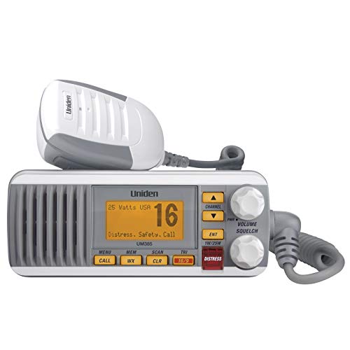
Uniden UM385 25 Watt Fixed Mount Marine Vhf Radio, Waterproof IPX4 with Triple Watch, Dsc, Emergency/Noaa Weather Alert, All Usa/International/Canadian Marine Channels, Memory Channel Scan, White
Uniden UM385 25 Watt Fixed Mount Marine Vhf Radio, Waterproof IPX4 with…
VIEW LATEST PRICE
Retevis RM20 Marine VHF Radios Fixed Mount, Marine Band Radio with Built in GPS, DSC, IP67 Waterproof, High Power, NOAA Weather, International Channels, Ship to Shore Radio for Boats(Black)
Retevis RM20 Marine VHF Radios Fixed Mount, Marine Band Radio with Built…
VIEW LATEST PRICEMounting Style Comparison
| Feature | Bracket Mount | Flush Mount |
|---|---|---|
| Visibility | High (Adjustable angles) | Integrated (Fixed angle) |
| Space Required | More (Depth + Clearance) | Minimal (Surface level) |
| Ease of Removal | Fast (Thumb screws) | Difficult (Requires tools) |
| Aesthetics | Functional/Rugged | Clean/Factory look |
| Cooling | Excellent airflow | Limited (Requires venting) |
When choosing your best fixed-mount VHF marine radio, consider the depth behind the dashboard. Many modern units are shallow, but you still need at least two inches of clearance for the power and antenna cables to bend without stress. Avoid placing the radio within three feet of your magnetic compass. The internal speaker and electronic components contain magnets that can cause significant deviation, leading to inaccurate navigational readings. Use a template to mark your drill holes and verify that no existing wiring or plumbing exists behind the mounting surface.
Choose and Mount the Correct VHF Antenna
VHF radio range is primarily a function of antenna height and gain because the signals operate on a line-of-sight basis. You should mount your antenna as high as possible, such as on a T-top, radar arch, or sailboat mast. For most powerboats under 30 feet, an 8-foot fiberglass antenna with 6dB gain provides the best balance of range and stability. Sailboats typically use a 3-foot stainless steel “whip” antenna with 3dB gain mounted at the masthead to minimize the effects of the boat’s healing.
Antenna Selection Criteria
- 6dB Gain: Best for powerboats; focuses the signal toward the horizon in a flatter, wider pattern.
- 3dB Gain: Best for sailboats; creates a more spherical signal pattern that stays on the horizon even when the boat tips.
- Fiberglass Material: Offers durability and internal protection for the radiating element.
- Stainless Steel: Lightweight and flexible, ideal for high-vibration or high-wind environments.
Secure the antenna base using a heavy-duty stainless steel ratcheting mount. This allows you to fold the antenna down when passing under low bridges or during trailering. Ensure the mount is bolted through the deck or hardtop with a backing plate to distribute the load. Applying a small amount of marine sealant like 3M 4200 to the bolt holes prevents water from seeping into the core of your boat. For those using a best marine VHF radio handheld as a backup, remember that its range is significantly lower due to the lack of height and gain compared to a fixed antenna.
Establish a Clean Power Connection to the Battery
A fixed-mount VHF radio requires a direct connection to a 12-volt DC power source using marine-grade tinned copper wire to ensure consistent performance. You should avoid tapping into existing light circuits or accessory wires, as these often lack the amperage capacity to support a radio during a 25-watt transmission. Connect the positive (red) wire to a dedicated terminal on your fuse block or directly to the battery switch. The negative (black) wire must go to a common ground bus bar or the negative battery terminal.
Wiring Gauge Requirements (12V System)
- 0-10 Feet: 16 AWG (Standard for most small boats).
- 10-20 Feet: 14 AWG (Reduces voltage drop over longer runs).
- 20+ Feet: 12 AWG (Necessary for large cruisers or trawlers).
Voltage drop is the enemy of radio performance. If the voltage at the back of the radio falls below 11.5 volts during transmission, your signal strength will plummet, and the radio may even shut down. Use heat-shrink butt connectors or ring terminals for every junction. These provide a mechanical bond and a watertight seal that prevents the “wicking” of saltwater into the wire strands. Always install the fuse provided by the manufacturer in the positive line. This fuse protects the radio’s sensitive internal circuitry from spikes and prevents the wiring from overheating in the event of a short circuit.
Route the Coaxial Cable for Maximum Signal Integrity
Proper coaxial cable routing involves avoiding sharp bends and keeping the cable away from other high-current electrical wires to prevent electromagnetic interference. You should use RG-58 cable for short runs (under 20 feet) and RG-8X or RG-213 for longer runs to minimize signal loss. Every foot of cable introduces a small amount of “attenuation” or loss, so keep the run as short as practical while maintaining a clean path. Avoid coiling excess cable into tight loops; if you have extra length, lay it in a loose “figure-eight” pattern to prevent it from acting as an inductor.
Cable Protection Steps
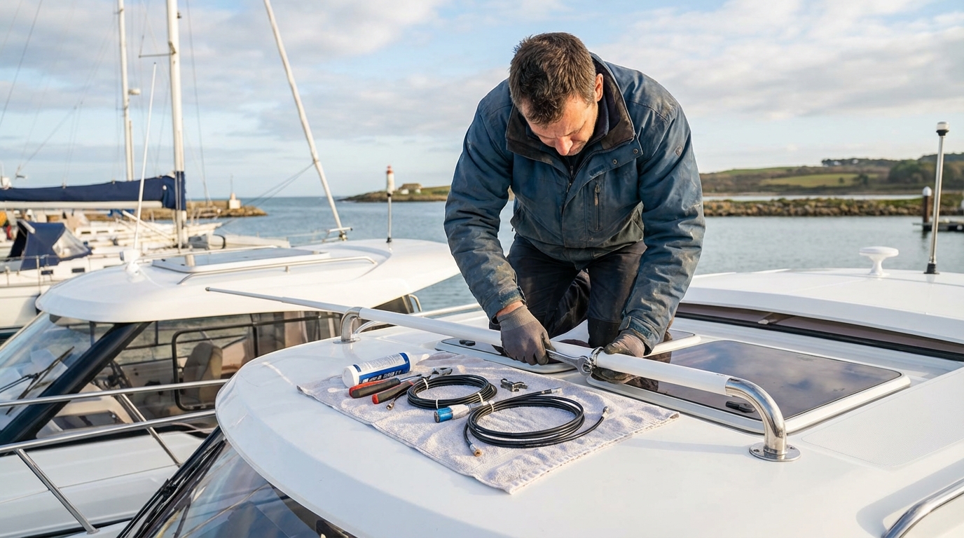
- Use Grommets: Place rubber grommets in any hole drilled through fiberglass or metal to prevent the sharp edges from chafing the cable jacket.
- Support the Cable: Use plastic cable clamps every 18 inches to secure the line and prevent it from vibrating or sagging.
- Seal the Exit: Apply a clamshell cover or a dedicated cable seal where the wire passes from the exterior to the interior.
- Avoid Power Lines: Maintain at least six inches of separation from engine battery cables and alternator wires.
When installing a fixed-mount marine radio, pay close attention to the PL-259 connector. This is the most common point of failure in marine communication systems. If your antenna came with a pre-installed connector, protect it with a plastic bag while pulling it through the boat. If you must cut the cable to route it, you will need to install a new connector. Most experts prefer a solder-on connector for its electrical continuity, though modern “centerpin” crimp connectors are becoming popular for their ease of installation without a soldering iron.
Integrate GPS and NMEA Networking for DSC Functionality
Modern VHF radios must be connected to a GPS source to enable Digital Selective Calling (DSC), which transmits your vessel’s location during an emergency. You can achieve this by connecting the radio to your chartplotter using either NMEA 0183 or NMEA 2000 networking protocols. NMEA 2000 is the modern standard, utilizing a simple “plug-and-play” backbone system with standardized Micro-C connectors. If your radio and GPS both support NMEA 2000, you simply plug both into the same network backbone, and they will share data instantly.
NMEA 0183 Wiring Color Codes (Typical)
- Yellow: NMEA In (+) – Receives GPS data from the plotter.
- Green: NMEA In (-) – The ground for the incoming data signal.
- White: NMEA Out (+) – Sends DSC data to the plotter (to show other boats on your screen).
- Brown: NMEA Out (-) – The ground for the outgoing data signal.
If you are using NMEA 0183, you must manually strip and twist the tiny data wires together, then secure them with waterproof connectors. Correct integration is verified when the radio display shows your current latitude and longitude. Without this connection, the red “Distress” button on your radio is significantly less effective, as the Coast Guard will receive your signal but not your location. Some higher-end radios include a built-in GPS receiver and antenna, which eliminates the need for external wiring but requires the radio to have a clear view of the sky or be mounted near a window.
Assemble the Necessary Tools and Materials
A successful VHF installation requires a specific set of marine-grade tools to ensure the connections survive the harsh vibration and moisture of the boating environment. You should gather your supplies before starting to avoid mid-project trips to the hardware store. Standard automotive tools are often insufficient because they lack the corrosion resistance needed for saltwater applications.
Installation Tool Checklist
- Electric Drill and Bits: For mounting holes and cable pass-throughs.
- Hole Saw: If you are flush-mounting the radio into the dashboard.
- Wire Strippers and Crimpers: High-quality ratcheting crimpers are preferred for consistent terminal pressure.
- Heat Gun: For shrinking the insulation on waterproof connectors.
- Soldering Iron: Required if you are attaching a traditional PL-259 antenna connector.
- Multimeter: Essential for checking voltage and testing for continuity or shorts.
- Marine Sealant: 3M 4200 or 4000UV for sealing deck penetrations.
Using the right materials is just as important as the tools. Ensure all screws and bolts are Grade 316 stainless steel to prevent rust streaks on your gelcoat. When proper VHF radio installation is the goal, using tinned copper wire is non-negotiable. Standard copper wire will turn green with “black wire disease” within a single season, leading to high resistance and equipment failure. Tinned wire has a thin coating of tin over each individual strand, which blocks oxidation and keeps the electrical path clear.
Install the PL-259 Connector with Precision
The PL-259 connector connects the coaxial antenna cable to the back of the radio and must be installed with zero short circuits between the center conductor and the outer shield. You start by stripping the outer jacket of the coax cable to reveal the braided shield, then peeling back the shield to expose the inner dielectric and the center copper wire. The most common mistake is allowing a single tiny strand of the braided shield to touch the center conductor, which creates a “short” and prevents the radio from transmitting.
Soldering the PL-259 Connector
- Slide the Shell: Always slide the outer coupling ring onto the cable before you attach the connector body.
- Tin the Wire: Apply a small amount of solder to the center conductor to keep the strands together.
- Insert the Cable: Push the cable into the connector body until the center conductor sticks out of the tip.
- Solder the Tip: Apply heat to the connector tip and feed solder in until the center wire is fully bonded.
- Solder the Shield: High-quality connectors have “weep holes” in the side where you can solder the braid to the connector body.
Once the soldering is complete, use your multimeter to check for continuity. There should be zero ohms of resistance between the center pin at one end of the cable and the center pin at the other. There should be infinite resistance (an open circuit) between the center pin and the outer threaded shell. If your meter shows any connection between the two, you have a short and must redo the connector. Poorly installed connectors are the primary cause of “weak” signals and blown radio power modules.
Mount the Radio Using Flush or Bracket Methods
Bracket mounting is the most versatile method for installing a VHF radio, allowing you to tilt the unit for better visibility and remove it easily for storage. You begin by securing the U-shaped bracket to your chosen surface with stainless steel self-tapping screws or through-bolts. Once the bracket is firm, you slide the radio into the cradle and tighten the plastic thumb knobs on the sides. This method is excellent for mounting on top of a console or underneath an overhead electronics box.
Flush Mount Installation Steps
- Tape the Template: Secure the manufacturer-provided paper template to the dashboard with masking tape.
- Drill Pilot Holes: Drill small holes in the corners of the cutout area to allow a jigsaw blade to enter.
- Cut the Opening: Use a fine-tooth jigsaw blade to cut along the lines of the template, taking care not to scratch the surrounding dash.
- Test Fit: Insert the radio to ensure it sits flush; trim the edges of the hole with a file if necessary.
- Secure the Unit: Use the provided mounting studs and nuts from behind the dash to pull the radio tight against the surface.
Flush mounting provides a clean, professional appearance that integrates the radio into the boat’s design. However, it requires a permanent hole in your dashboard and limits airflow around the unit. If you choose this method, ensure there is sufficient ventilation behind the helm to dissipate the heat generated during long transmissions. Most modern radios include a foam gasket to provide a water-resistant seal between the radio face and the mounting surface, but a thin bead of silicone can offer extra protection in high-exposure areas.
Test the System and Check the SWR
After the physical installation is complete, you must verify that the radio receives and transmits correctly using a series of tests. Start by powering the unit on and checking the display for any error messages, such as “Antenna Error” or “No GPS.” Check the squelch control to ensure the internal speaker is functioning; you should hear white noise when the squelch is turned all the way down. Use the how to test your VHF radio guide to perform a “Radio Check” on a non-emergency channel like Channel 09 or a local automated radio check service.
Interpreting SWR (Standing Wave Ratio) Readings
| SWR Ratio | Meaning | Action Required |
|---|---|---|
| 1.0:1 to 1.5:1 | Perfect Connection | None – System is optimized. |
| 1.5:1 to 2.0:1 | Good/Acceptable | Standard for most marine setups. |
| 2.0:1 to 3.0:1 | Poor Efficiency | Check connectors for moisture or corrosion. |
| Above 3.0:1 | Critical Failure | Do not transmit; risk of damaging the radio. |
An SWR meter is the most accurate way to test your antenna system. It measures how much of the radio’s energy is actually being sent out through the antenna versus how much is being reflected back into the radio. High SWR indicates a problem with the antenna, the cable, or the connectors. Most marine antennas are factory-tuned and cannot be adjusted, so if your SWR is high, the fault almost always lies in a poorly installed PL-259 connector or a crushed section of coaxial cable.
Register Your MMSI and Program the Radio
A Maritime Mobile Service Identity (MMSI) is a unique nine-digit number that acts like a phone number for your boat’s radio and is required for DSC features to work. You can obtain an MMSI number for free or a small fee through organizations like BoatUS or the United States Power Squadrons if you plan to stay in domestic waters. If you intend to cruise to international ports (including Canada or the Bahamas), you must obtain your MMSI through the FCC as part of a Ship Station License.
MMSI Programming Guidelines
- One-Time Entry: Most VHF radios only allow you to enter the MMSI number once or twice. If you make a mistake, the unit must be sent back to the manufacturer for a factory reset.
- Accuracy: Double-check every digit before hitting the “Enter” or “Confirm” button on your radio.
- Emergency Contact: Ensure your registration includes up-to-date emergency contact information, as the Coast Guard uses this data during rescue operations.
- Transfer of Ownership: If you sell your boat, you must cancel your MMSI registration or transfer it to the new owner so the radio is linked to the correct person.
Once the MMSI is programmed, your radio can send an automated distress signal that includes your identity and location at the touch of a button. It also allows you to make “private” calls to other boats by entering their MMSI numbers, causing their radio to ring like a telephone. This feature is part of the Global Maritime Distress and Safety System (GMDSS), which has revolutionized marine safety by reducing the time it takes for rescuers to find a vessel in trouble.
Prevent Waterproofing Failures and Corrosion
Waterproofing is the final and most critical step in an installation because salt air and water will eventually destroy any unprotected electrical connection. You should use adhesive-lined heat shrink tubing on every wire terminal. Unlike standard heat shrink, the adhesive-lined variety melts and flows into the gaps as you heat it, creating a truly airtight and watertight seal. This prevents the “wicking” effect where saltwater travels up the inside of the wire insulation, rotting the copper from the inside out.
Sealing Points for VHF Installations
- Antenna Base: Apply sealant to the bolt holes and the cable exit hole.
- Cable Pass-Through: Use a “deck gland” or “cable seal” rather than just a blob of silicone for a long-lasting seal.
- Terminal Connections: Coat battery terminals and bus bar connections with a thin layer of dielectric grease or a dedicated terminal protector spray.
- Connector Threads: Apply a small amount of silicone grease to the threads of the PL-259 connector to prevent it from seizing over time.
Corrosion often hides behind the dashboard where you cannot see it. Regular inspections are necessary to ensure that your grounding points remain clean and tight. If you notice a white, powdery substance on your terminals, clean them with a wire brush and re-apply protection. A well-sealed system can last over a decade, while a poorly sealed one may fail during your first major storm. Understanding how to use a VHF radio on a boat effectively starts with the confidence that your equipment is physically sound.
Manage Electromagnetic Interference (EMI) and Grounding
Electromagnetic interference (EMI) can cause “buzzing” or “humming” on your radio, which is often generated by the engine’s alternator, LED lighting, or nearby fishfinders. You can minimize this by ensuring your radio is properly grounded and by using shielded cables where possible. If the noise persists only when the engine is running, you may need to install an inline power filter on the radio’s 12-volt supply line to “smooth out” the electrical noise from the alternator.
Methods to Reduce Interference
- Twisted Pair Wiring: Twisting the positive and negative power wires together can help cancel out magnetic fields.
- Ferrite Beads: Clipping a ferrite core onto the power and data cables near the back of the radio can block high-frequency noise.
- Separation: Keep your VHF antenna at least three feet away from GPS antennas and radar scanners.
- Dedicated Ground: While most marine radios use the negative power wire as a ground, some have a separate grounding lug on the back. Connect this to the boat’s common grounding system to bleed off static and interference.
EMI is particularly common on modern boats packed with digital electronics. If you hear a “ticking” sound, it is likely coming from your depth sounder’s transducer. If you hear a high-pitched whine that changes with engine RPM, it is the alternator. Identifying the source of the noise is the first step; shielding or relocating the offending wire or device is the second. A clean signal is essential for hearing weak transmissions from distant vessels or the Coast Guard.
Finalizing Your Marine Communication Setup
Installing your VHF marine radio correctly is an investment in your safety that pays dividends every time you leave the dock. By prioritizing antenna height, using marine-grade tinned wiring, and ensuring a solid NMEA connection for DSC, you create a reliable lifeline to the outside world. At VHF Radio (Marine Guide), we have seen that the most common communication failures stem from small oversights, like unsealed connectors or improper wire gauges. Take the time to do it right, test your SWR, and register your MMSI. Once your system is operational, you can navigate with the peace of mind that help is always just a radio call away, whether you are in a crowded harbor or miles offshore.
📅 Last updated: