
The most reliable way to test a VHF marine radio antenna is to measure the Standing Wave Ratio (SWR) using an inline SWR meter to ensure power is radiating into the atmosphere rather than reflecting back into the radio. Testing involves a three-pronged approach: a physical inspection of the coaxial cable and connectors, a continuity test using a multimeter to check for internal shorts, and a functional radio check to verify clear transmission and reception over a known distance.
Your VHF radio is only as good as the antenna system connected to it. Even the most expensive fixed-mount unit will fail to transmit more than a mile if the antenna has internal corrosion or a compromised cable. Whether you are preparing for a long offshore passage or just performing routine seasonal maintenance in March 2026, understanding the health of your antenna system is the difference between a successful distress call and total silence. At VHF Radio (also uses ‘Marine Guide’), we focus on providing the practical data you need to maintain your electronics without the guesswork.
Marine Radio Antenna Testing Tools

Mcbazel Surecom SW-102 Digital VHF/UHF 125-525Mhz Antenna Power & SWR Meter
Mcbazel Surecom SW-102 Digital VHF/UHF 125-525Mhz Antenna Power & SWR Meter
VIEW LATEST PRICE
Mcbazel Surecom SW-33 Plus 100W 125-525 MHz Mini Digital VHF UHF Two-Way Radio Handheld Power & SWR Meter Black
Mcbazel Surecom SW-33 Plus 100W 125-525 MHz Mini Digital VHF UHF Two-Way…
VIEW LATEST PRICE
Surecom Gam3Gear SW-102S SO239 Connector Digital VHF UHF 125-525Mhz Power & SWR Meter
Surecom Gam3Gear SW-102S SO239 Connector Digital VHF UHF 125-525Mhz Power & SWR…
VIEW LATEST PRICEPhysical Inspection of the Antenna Mast and Whip
A visual inspection identifies structural failures like fiberglass blooming or stress cracks that allow moisture to penetrate the antenna’s internal radiator. Before connecting any electronic testing equipment, you must verify that the physical structure of the antenna is sound, as internal moisture is the leading cause of “phantom” signal issues that appear and disappear with the weather.
Start at the base of the antenna. Look for any signs of “blooming”—a condition where the fiberglass resin breaks down, exposing raw fibers. These fibers act like a wick, pulling salt water into the core of the antenna. If you see white, fuzzy fibers or deep yellowing, the antenna is likely compromised. Check the mounting bracket for stability; a loose mount causes the antenna to whip excessively, which can fatigue the internal solder joints.
For stainless steel whip antennas, check for permanent bends or kinks. While a slight curve won’t destroy performance, a sharp 90-degree kink can change the resonance of the whip, shifting the SWR out of the safe range. Ensure the whip is seated firmly in its base. Many antennas use a small set screw to hold the whip in place; if this is loose, you will experience intermittent signal loss while underway in choppy water.
Evaluating Coaxial Cable Integrity
The coaxial cable (coax) acts as the bridge between your radio and the antenna, and any physical damage to its outer jacket will eventually lead to signal loss through attenuation. Marine environments are harsh on plastics, and UV degradation can make a once-flexible cable brittle and prone to cracking.
Inspect the entire length of the cable from the back of the radio to the antenna base. Look for “green death”—a term mariners use for the green copper oxide that forms when moisture enters the cable. If the copper shielding looks dull or green rather than bright and shiny, the cable’s impedance has changed, and it must be replaced.
Avoid tight bends. Coaxial cable has a minimum bend radius, usually about five times its diameter. If a cable is pinched in a locker or bent at a sharp angle to pass through a bulkhead, the internal dielectric (the white plastic insulation) can be crushed. This brings the center conductor closer to the outer shield, creating a “bump” in the electrical path that reflects power back to the radio. Using proper marine VHF radio usage techniques includes ensuring your hardware is installed without these physical stressors.
Testing PL-259 Connectors and Soldered Joints
The PL-259 connector is the most common point of failure in a marine VHF system due to improper soldering or moisture ingress at the terminal. Because these connectors are often exposed to salt spray, they are highly susceptible to galvanic corrosion which increases resistance and degrades the signal.
Unscrew the connector from the back of the radio and look inside. The center pin should be bright and free of oxidation. If you see white powder or green crust, the connection is failing. A professional-grade connection should have solder visible through the small holes in the side of the connector (the “solder windows”). If the connector was “crimp-only,” check that the crimp remains tight and hasn’t loosened due to vibration.
Weatherproofing is non-negotiable for external connections. If the connection at the antenna base is exposed to the elements, it should be wrapped in self-vulcanizing rubber tape followed by a layer of high-quality electrical tape. If you find a connector that was left bare, it is safer to cut it off, trim the cable back to fresh copper, and install a new connector rather than trying to clean the old one.
Using a Multimeter for Continuity and Resistance Checks
A multimeter allows you to check for a “DC Short” or an “Open Circuit” in your antenna system, providing a quick way to diagnose a completely dead antenna. To perform this test, you must first know if your antenna is “DC Grounded” or “Open,” a specification usually found in the manufacturer’s manual.
Set your multimeter to the Ohms (Ω) setting. Place one probe on the center pin of the PL-259 connector and the other probe on the outer threaded shell.
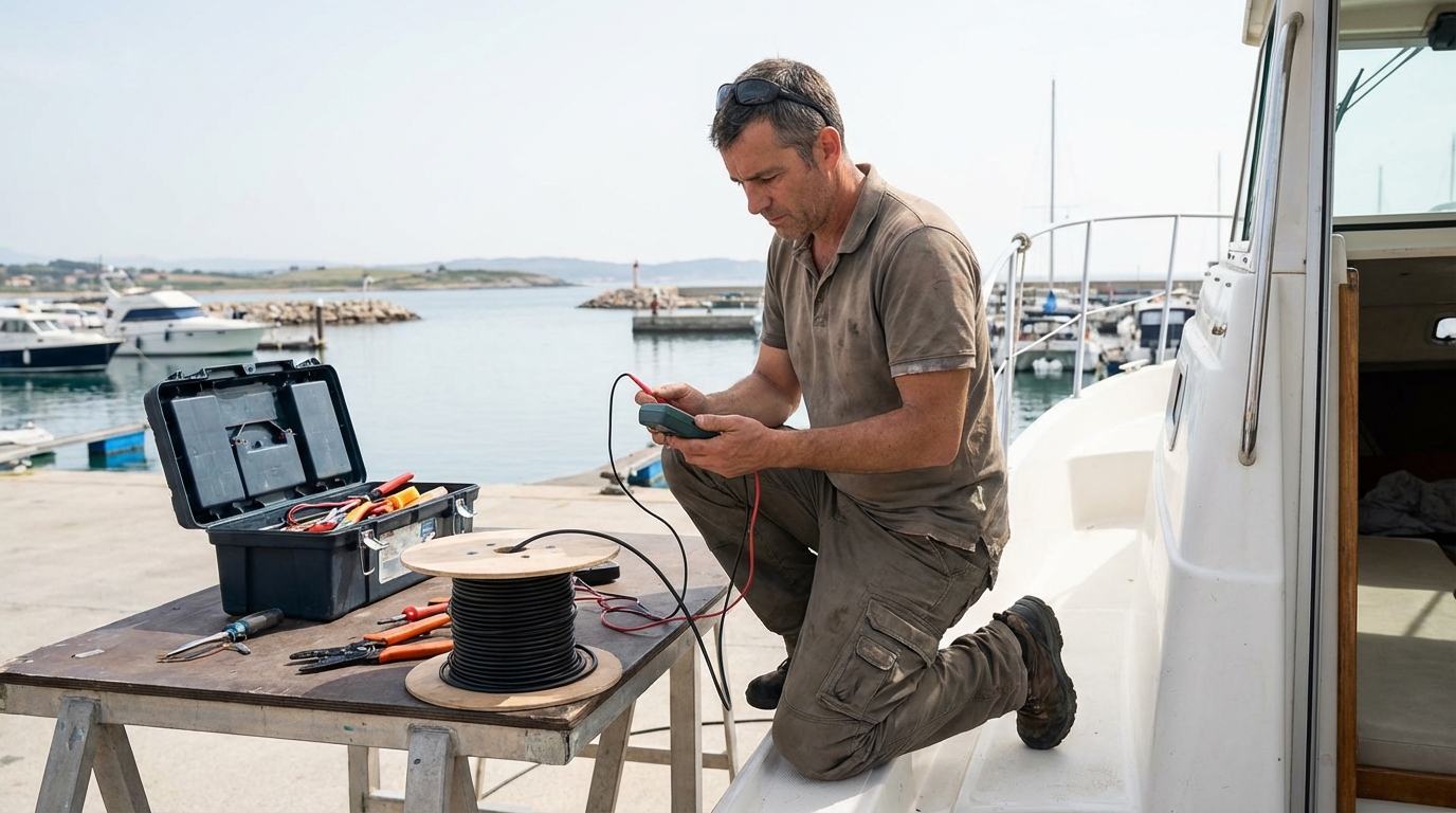
- For “Open” Antennas (Standard): The meter should read “Infinite” or “OL” (Open Loop). This means there is no direct connection between the center wire and the shield. If you get a low resistance reading, you have a short circuit, usually caused by a stray strand of wire touching the center pin inside the connector.
- For “DC Grounded” Antennas: The meter should read a very low resistance (near 0 ohms). These antennas have an internal coil that connects the radiator to the ground for lightning protection.
Next, test the continuity of the cable itself. If possible, have someone hold a jumper wire at the antenna end to short the center and shield together, then test from the radio end. You should see near-zero resistance. According to Practical Boat Owner’s guide on testing old antennas, a multimeter is an essential first-step tool, though it cannot tell you how the antenna performs at high frequencies; for that, you need an SWR meter.
Measuring Standing Wave Ratio (SWR)
SWR measurement is the gold standard for antenna testing because it tells you exactly how much of your 25-watt transmit power is actually leaving the antenna. A high SWR means power is reflecting back into the radio’s final power amplifier, which can cause the radio to overheat or even blow its internal circuitry.
To use an SWR meter, you insert it “inline” between the radio and the antenna. You will need a short “patch cable” (usually 3 feet of RG-58 coax with PL-259 connectors on both ends). Connect the radio to the “TX” or “Transmitter” port on the meter, and the antenna cable to the “ANT” or “Antenna” port.
Switch the radio to a low-traffic channel (like Channel 72) and set the power to “High” (25W). Flip the meter switch to “Forward” and key the mic to calibrate the needle to the set point. Then, flip the switch to “Reflected” or “SWR.” A reading of 1.5:1 or lower is excellent. A reading above 2.0:1 indicates a problem that needs investigation, and anything above 3.0:1 is critical—stop transmitting immediately to avoid damaging your radio.
Interpreting SWR Reading Values
Understanding SWR values is crucial for determining whether your antenna system requires a simple tune-up or a total replacement. These ratios represent the efficiency of the impedance match between your 50-ohm radio and your antenna.
| SWR Ratio | Efficiency | Meaning | Action Required |
|---|---|---|---|
| 1.0:1 to 1.3:1 | 98% – 100% | Perfect Match | None. System is optimized. |
| 1.5:1 | 96% | Good | Normal for most marine installations. |
| 2.0:1 | 89% | Acceptable but Marginal | Check connectors for moisture or corrosion. |
| 3.0:1 | 75% | Poor | Serious mismatch. Check for cable damage or shorts. |
| 5.0:1+ | <50% | Dangerous | Do not use. Likely a broken wire or dead short. |
If your SWR is high across all channels, the problem is likely in the cable or the antenna itself. If the SWR is low on Channel 01 but high on Channel 88, the antenna is “long” and may need its whip trimmed (though most marine antennas are factory-tuned and not adjustable).
Performing a Functional Radio Check
A functional radio check confirms that the entire system—radio, mic, cable, and antenna—is working together to produce clear audio over a distance. While electronic meters give you data, a radio check gives you real-world confirmation that your signal is intelligible to other mariners.
In the past, mariners used Channel 16 for radio checks, but this is now discouraged as it clogs the distress and hailing frequency. Instead, use Channel 09 or a designated “working channel” used by local marinas. State your vessel name, your location, and ask for a “radio check.”
A better method is to use an automated radio check service if available in your area. Some organizations provide automated stations that record your transmission and play it back to you. This allows you to hear exactly how you sound—whether there is a hum from engine interference or if your audio is “thin” due to a failing microphone element. As noted in the Elite Offshore Academy’s marine radio check guide, performing these checks regularly is a core part of maritime safety protocol.
Advanced Testing with an Antenna Analyzer
An antenna analyzer is a more sophisticated tool than an SWR meter because it can show you the resonance and impedance of the antenna across a wide range of frequencies without needing the radio to transmit. This is the preferred tool for professional installers because it can identify exactly where an antenna is tuned.
While an SWR meter only tells you if something is wrong, an analyzer can tell you what is wrong. For example, if the analyzer shows that the antenna is resonant at 145 MHz (the Ham radio band) instead of 156 MHz (the Marine band), you know you have the wrong antenna for the application. It can also measure “Return Loss” in decibels (dB), which is a more precise way of looking at reflected power.
For most boaters, an analyzer is a luxury. However, if you are troubleshooting a complex mast-top installation on a sailing vessel where the cable run is 60+ feet, the analyzer can help determine if the cable’s loss is the primary issue rather than the antenna itself.
Testing Handheld vs. Fixed Mount Antennas
Testing a handheld VHF antenna requires a different approach because the antenna (rubber ducky) is designed to use the radio’s body and your hand as a “ground plane.” Handheld antennas are notoriously difficult to test with standard SWR meters because adding a meter and a cable changes the very physics of how the antenna works.
The best way to test a handheld is through a “side-by-side” comparison. If you have a known-good handheld, stand in the same spot and call a shore station. If one radio receives the station clearly and the other doesn’t, swap the antennas. If the problem follows the antenna, you’ve found your culprit.
Keep in mind that handheld antennas are prone to internal wire breakage because they are frequently flexed. If the “rubber ducky” feels extra floppy or if you hear something rattling inside, the internal coil is likely snapped. For those looking for a replacement, checking marine VHF radio reviews can help you find high-gain aftermarket antennas that improve handheld range.
Impact of Antenna Height on Test Results
The height of your antenna is the single most important factor in your VHF range, but it can also complicate your testing if you are surrounded by obstructions. VHF signals are “line-of-sight,” meaning they do not follow the curve of the earth or penetrate heavy steel structures.
When testing your antenna at a marina, be aware of “multipath interference.” If you are docked next to a large steel-hulled ship or under a metal-roofed boathouse, the signal can bounce off these structures and return to your antenna. This can give you an artificially high SWR reading that disappears once you move into open water.
Always conduct your final SWR and radio check in a “clear” environment. If you are on a sailboat, the antenna is likely 30–60 feet in the air. This height provides a massive range advantage, but it also means there is a lot of cable (and potential for loss) between the radio and the tip. For a detailed look at the hardware used in these setups, see our guide on the best fixed mount VHF marine radio systems.
Identifying and Fixing Common Antenna Failures
Most antenna failures are not the result of the antenna “wearing out,” but rather a failure of the connections or the cable jacket. Understanding these common failure points allows you to fix the system for a few dollars in parts rather than hundreds for a new antenna.
- Moisture in the Coax: If the SWR rises during rain or high humidity, you have a leak. Replacing the connectors is the first step, but if the moisture has traveled more than a few inches down the cable, the cable is compromised.
- Corroded Shielding: If the outer braid of the coax is black or green, it will no longer conduct the signal efficiently. This adds “attenuation,” meaning your 25 watts of power is turned into heat inside the cable before it ever reaches the antenna.
- Broken Internal Radiator: In fiberglass antennas, the internal wire can break due to the mast’s vibration. This usually manifests as an intermittent signal—working fine at the dock but failing the moment you hit the chop.
- Static Build-up: In dry, windy conditions, an antenna can build up a static charge. A “DC Grounded” antenna prevents this, but an “Open” antenna might produce “popping” sounds in the receiver.
Seasonal Maintenance and Testing Schedule
Testing your VHF antenna shouldn’t be a “once every five years” event. A regular maintenance schedule ensures that small issues like a loose connector don’t turn into a total system failure during an emergency.
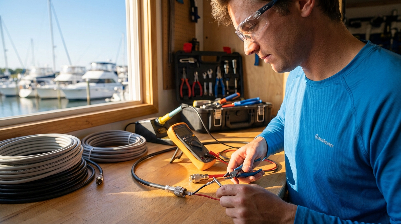
- Pre-Season (March/April): Perform a full visual inspection and an SWR test. Check all connectors for “green death.” This is the best time to replace a suspect cable while the boat is still on the hard.
- Mid-Season (July): Perform a long-distance radio check (5-10 miles). If you can’t reach a station you could reach in the spring, check your connectors for salt crust.
- Winterization (November): If you remove your antenna for the winter, coat the PL-259 threads with a light film of dielectric grease and cover the cable end with a waterproof cap or a small plastic bag and a rubber band.
For more information on general system health, refer to our comprehensive guide on how to test VHF radio units beyond just the antenna.
Antenna Gain and Its Role in Performance
Gain, measured in decibels (dB), refers to how an antenna concentrates its signal toward the horizon. When testing, you must understand the “radiation pattern” of your specific antenna to interpret why certain tests might fail.
A 3dB antenna (usually 3-4 feet long) has a broad, “round” radiation pattern. It is ideal for small boats that toss and turn in the waves, as the signal stays directed at the horizon even when the boat tilts. A 6dB or 9dB antenna (8-20 feet long) squashes the signal into a very flat, “pancake” shape. While this increases range significantly on a stable platform, the signal can actually “overshoot” the receiver if the boat heals over too far.
If you are testing a high-gain antenna and get poor results while the boat is rocking at the dock, it may simply be that your “signal pancake” is hitting the water or the sky rather than the testing station. Always test high-gain antennas when the boat is as level as possible.
Troubleshooting Interference and Noise Floor Issues
Sometimes an antenna tests “good” on an SWR meter, but the radio remains noisy or unable to hear distant stations. This is often due to an elevated “noise floor” caused by other electronics on your boat.
To test for local interference:
- Turn off every electronic device on the boat (GPS, Fishfinder, LED lights, Bilge pumps).
- Listen to a weak weather channel (one that is fuzzy).
- Turn on your electronics one by one.
- If the fuzziness turns into a loud buzz when you turn on your LED deck lights or your battery charger, you have RFI (Radio Frequency Interference).
This isn’t an antenna failure, but the antenna is “picking up” the noise from your own boat. Modern switching power supplies in cheap LED bulbs are a common culprit. Using shielded cables and ferrite chokes on the power wires of interfering devices can solve this without touching the antenna.
Essential Tools for Every Boater’s Kit
You don’t need a degree in electrical engineering to maintain your VHF system, but you do need a few specific tools. Relying on a “thumb’s up” from a neighbor at the dock is not a substitute for data.
- SWR Meter: Specific to the 156-163 MHz range. Don’t use a CB radio meter; they are tuned for 27 MHz and will give false readings.
- Digital Multimeter: For checking continuity and voltage at the radio’s power plug.
- PL-259 Soldering Kit: Including a high-wattage iron (at least 40W) because the large brass connectors act as a heat sink.
- Self-Vulcanizing Tape: For sealing external connections.
- Spare Connectors: Always keep two spare PL-259s and a “barrel” connector (F-to-F) in your emergency kit.
Maintaining these tools allows you to perform the same best handheld marine VHF radio and fixed-mount tests that professionals do.
The Future of Marine Antenna Technology
As we move further into 2026, we are seeing the rise of “Smart Antennas” and integrated AIS/VHF splitters that require even more precise testing. High-quality splitters allow one antenna to serve both your VHF radio and your AIS transponder, but they introduce a small amount of signal loss (usually about 3dB).
When testing a system with a splitter, you should test the SWR twice: once with the splitter in the line and once with the antenna plugged directly into the radio. If the SWR is fine direct-to-radio but spikes when the splitter is added, the splitter is faulty or the internal relay is failing.
Furthermore, the materials used in antenna construction are becoming more resilient. Newer carbon-fiber whips offer incredible rigidity and reduced weight, which is excellent for mast-top installations, but they require specific mounting hardware to avoid galvanic corrosion between the carbon and the aluminum mast. Always follow the manufacturer’s specific testing guidelines for these high-performance materials.
Summary of the Testing Process
Testing your VHF antenna is a logical progression from the physical to the electrical. Start with your eyes and hands, checking for cracks, corrosion, and loose mounts. Move to the multimeter to ensure there are no catastrophic shorts in the cable or connectors. Finally, use an SWR meter to verify that your radio’s power is efficiently reaching the airwaves.
A perfect SWR of 1.1:1 doesn’t matter if the antenna is mounted two feet above the water inside a metal cabin. Range is a product of Height + Integrity + Power. By verifying the integrity through the steps outlined above, you ensure that your height and power aren’t being wasted.
Keep your connectors dry, your cables unkinked, and your SWR below 2.0:1. If you follow these standards, your VHF radio will remain your most reliable safety tool on the water, providing clear communication when you need it most. For those ready to upgrade their entire communication suite, our expert reviews of the latest marine electronics provide a roadmap for modernizing your vessel’s capabilities.
📅 Last updated: