
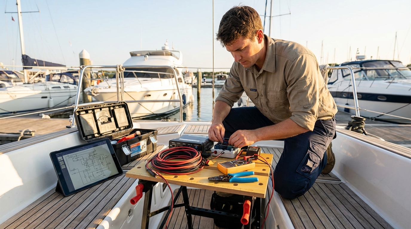
To install marine electronics successfully, you must create a detailed wiring plan, mount hardware in ergonomic locations, and establish a robust NMEA 2000 network for data sharing. This process requires using tinned copper wire to prevent corrosion, selecting the correct fuse sizes for each device, and ensuring all connections are sealed with adhesive-lined heat shrink. Whether you are adding a chartplotter, a fishfinder, or a fixed-mount VHF radio, following American Boat and Yacht Council (ABYC) standards ensures your system remains reliable in harsh saltwater environments.
Marine electronics are the brain and nervous system of your vessel. When they fail, you lose more than just your fish-finding capabilities; you lose navigation, communication, and safety. By handling the installation yourself, you gain an intimate understanding of your boat’s systems, which allows you to troubleshoot issues while offshore. This guide breaks down the complex world of marine tech into manageable steps, focusing on the methodology used by professional installers in March 2026.
Marine Electronics Installation Tools and Accessories
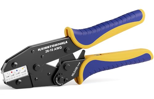
haisstronica Crimping Tool For Heat Shrink Connectors-AWG 26-10 Ratchet Wire Terminal Crimper-Ratcheting Crimper Tools-Available For Insulated Nylon Connectors and Electrical Wire Connectors HS-8327
haisstronica Crimping Tool For Heat Shrink Connectors-AWG 26-10 Ratchet Wire Terminal Crimper-Ratcheting…
VIEW LATEST PRICE
Ancor Marine Grade Products 703015 Angled Single Crimp Ratcheting Crimper – 22 AWG to 8 AWG, Blue/Black
Ancor Marine Grade Products 703015 Angled Single Crimp Ratcheting Crimper – 22…
VIEW LATEST PRICE
Preciva Wire Crimping Tool for Heat Shrink Connectors Kit, with 200PCS 22-10 AWG Heat Shrink Connectors,Ratcheting Crimper for Electrical, Automotive, Marine & Wiring Repairs
Preciva Wire Crimping Tool for Heat Shrink Connectors Kit, with 200PCS 22-10…
VIEW LATEST PRICEPlanning Your Marine Electronics Layout for Maximum Utility
Successful marine electronics installation begins with a mock-up of the helm to ensure all displays are within the pilot’s line of sight and reachable from the primary operating position. You should account for sun glare, physical obstructions like steering wheels or throttles, and the ergonomic “reach zone” to ensure you can operate touchscreens or buttons while the boat is in motion.
Before you drill a single hole, tape templates of your new Multi-Function Displays (MFDs) and radios to the dashboard. Sit in the captain’s chair and stand at the helm to verify that you can see the screens clearly in both positions. Consider the “dashboard real estate” carefully. Modern MFDs are getting larger, but you must leave room for essential analog backups or dedicated gauges if your engine data isn’t fully integrated.
A critical part of the planning phase is looking behind the scenes. Open the access hatches behind your console. Is there enough depth for the unit and its cable connectors? Many 12-inch MFDs require at least four to six inches of clearance behind the mounting surface for the cables to bend without straining the ports. If space is tight, you may need to use right-angle connectors or a pedestal mount rather than a flush mount.
Essential Tools for DIY Marine Electronics Installation
You cannot install marine electronics properly with standard automotive or household tools; you need specialized equipment designed for marine electrical work. Professional-grade ratcheting wire crimpers, heat guns, and high-quality wire strippers are mandatory to create the gas-tight, corrosion-resistant connections required by the ABYC.
Here is a list of the non-negotiable tools you will need:
- Ratcheting Wire Crimper: Unlike “crush” crimpers, these ensure a consistent, high-pressure crimp every time.
- Heat Gun: Used for shrinking adhesive-lined terminals to create a waterproof seal.
- Digital Multimeter: Essential for testing voltage, continuity, and grounding.
- Fish Tape or Glow Rods: Used for pulling wires through tight rigging tubes and chases.
- Hole Saws and Drill Bits: Specifically sized for your MFD’s flush-mount dimensions or transducer cables.
- Label Maker: To identify every wire at both the source and the destination.
Using the wrong tools is the leading cause of “ghost in the machine” electronic failures. For example, using standard electrical tape instead of heat shrink allows salt air to penetrate the copper strands, leading to “black wire disease,” where corrosion travels up the wire under the insulation, eventually killing the device.
Designing a Marine Electrical System That Won’t Fail
A reliable marine electrical system relies on a dedicated power distribution point that separates sensitive electronics from high-draw engine cranking circuits. To prevent “voltage sag” or “brownouts” when you start your engines, you should install a dedicated “house” battery bank and a clean power circuit specifically for your electronics.
Following a beginner’s guide to your boat’s tech helps you understand that electronics are highly sensitive to voltage fluctuations. When an engine cranks, it can pull the battery voltage down to 9V or 10V, which may cause your GPS or sonar to reboot.
To avoid this, run a 4-gauge or 6-gauge “backbone” wire from your house battery to a dedicated fuse block under the console. This fuse block acts as the central hub for your electronics. From here, you can run individual, fused wires to each unit. This setup simplifies troubleshooting and ensures that a short circuit in your LED lights won’t take out your navigation system.
Choosing the Right Wire Gauge for Marine Environments
Selecting the correct wire gauge is determined by the total amperage draw of the device and the round-trip distance from the power source. For marine electronics, you must use tinned copper wire (Type III) that meets UL 1426 standards, as raw copper will oxidize and fail rapidly in a moist environment.
| Total Amperage | 10 Feet (3m) | 20 Feet (6m) | 30 Feet (9m) |
|---|---|---|---|
| 5 Amps | 16 AWG | 14 AWG | 12 AWG |
| 10 Amps | 14 AWG | 12 AWG | 10 AWG |
| 15 Amps | 12 AWG | 10 AWG | 8 AWG |
| 20 Amps | 10 AWG | 10 AWG | 8 AWG |
Note: Calculations based on a 3% voltage drop for critical electronics.
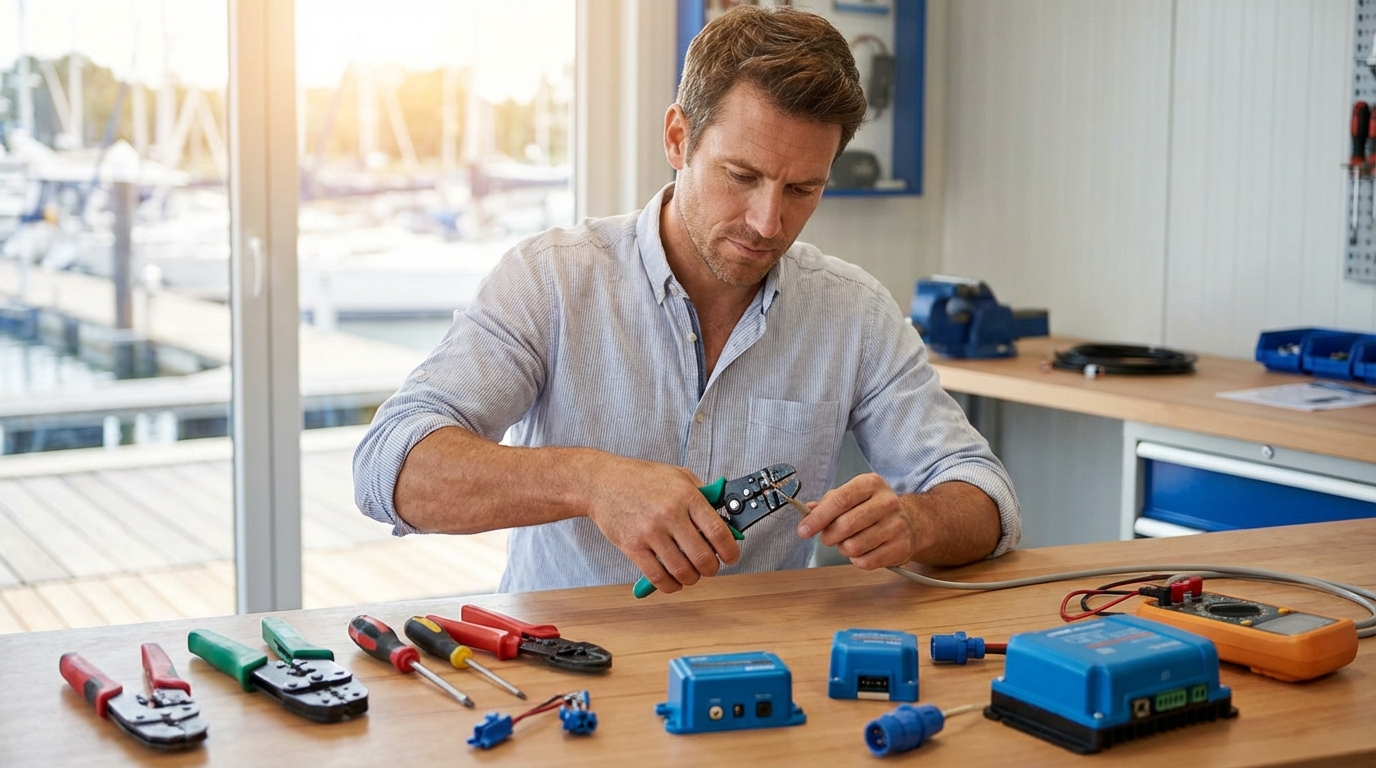
Voltage drop is the enemy of electronics. Even if a device “works” on undersized wire, it may experience software glitches, reduced sonar sensitivity, or dim screens. Always round up to the next wire size if you are on the border of a calculation.
How to Mount Displays and Multi-Function Displays (MFDs)
Mounting an MFD involves choosing between a flush mount, which sits flat against the dash, or a bracket mount, which allows for tilt and swivel adjustments. Flush mounting provides a sleek, factory-finished look but requires permanent cutting of the dashboard and offers less flexibility for viewing angles.
If you choose to flush mount:
- Check for obstructions: Ensure no wiring or structural supports are behind the cut area.
- Use the template: Most manufacturers provide a paper template. Tape it down and level it with a spirit level.
- The “Pilot Hole”: Drill small holes in the corners of the cutout area first.
- Cutting: Use a jigsaw with a fine-tooth blade for fiberglass or a specialized bit for acrylic dashes.
- Sealing: Apply a thin bead of marine-grade silicone or use the provided foam gasket to prevent water from leaking behind the dash.
If you opt for a bracket mount, ensure the mounting surface is reinforced. A 12-inch MFD can weigh several pounds, and the pounding of waves creates significant G-forces that can rip screws out of thin fiberglass. Use a backing plate made of Starboard or aluminum for added security.
Installing Transducers: Thru-Hull vs. Transom Mount
Installing a transducer requires finding a location on the hull with “clean” water flow, free from the turbulence and air bubbles created by strakes, rivets, or steps. For transom-mount transducers, this typically means the starboard side of the boat (on single-engine outboards) to avoid the downward sweep of the propeller’s rotation.
Transom Mount Transducers
Transom mounts are popular for smaller boats and are easier to install. However, they are prone to “rooster tails” and losing the signal at high speeds if not positioned perfectly. The transducer should be slightly below the hull’s bottom edge, angled just a few degrees forward to ensure the face stays in contact with solid water.
Thru-Hull Transducers
Thru-hull transducers offer the best performance but require drilling a large hole through the bottom of your boat. This is often intimidating for DIYers, but it provides the clearest sonar image. You must use a high-performance marine sealant like 3M 5200 for below-waterline applications. Ensure the transducer is mounted vertically; if your hull has a significant V-shape (deadrise), you will need a tilted-element transducer or a fairing block to compensate for the angle.
According to best practices for installing marine electronics, you should never run transducer cables alongside power cables. The high-frequency signals in the transducer cable are susceptible to electromagnetic interference (EMI), which appears as “noise” or “snow” on your sonar screen.
Networking Your Marine Electronics via NMEA 2000
The NMEA 2000 (N2K) network is the industry standard for allowing different brands and types of electronics to communicate, sharing GPS data, engine metrics, and AIS information across the entire boat. An N2K network consists of a “backbone” with “T-connectors” and “terminators” at each end to prevent signal reflection.
To build a basic NMEA 2000 network:
- Establish the Backbone: Run the main N2K cable through the center of the boat or under the console.
- Power the Network: The network requires its own 12V power source, usually connected to a T-connector in the middle of the backbone.
- Add T-Connectors: Every device (MFD, VHF, Autopilot) requires its own T-connector.
- Connect Drop Cables: Run a drop cable (no longer than 6 meters/20 feet) from the T-connector to the device.
- Install Terminators: You MUST have one male and one female terminator at the absolute ends of the backbone for the network to function.
A common mistake is creating “circles” in the network or forgetting the terminators. Without proper termination, data packets collide, leading to intermittent connection issues where your VHF might show GPS data one minute and “No Signal” the next.
Integrating VHF Radios and Antennas for Peak Performance
A fixed-mount VHF radio is your most important piece of safety gear, and its performance depends entirely on the quality of its antenna and the height of its mount. When installing a best fixed mount vhf marine radio, you must ensure the antenna has a clear 360-degree “view” of the horizon, away from large metal objects or other antennas that could cause interference.
The VHF radio should be mounted within easy reach of the helm but far enough from the compass to avoid magnetic interference (usually 2-3 feet). When routing the coaxial cable (usually RG-58 or RG-8X), avoid sharp bends or kinks, which can damage the internal shielding and reduce your transmission range.
If you are unfamiliar with radio operation, learning how to use a vhf radio on a boat is the next logical step after installation. You will need to program your Digital Selective Calling (DSC) MMSI number into the unit to enable the emergency distress button, which requires the radio to be networked to your GPS via NMEA 0183 or NMEA 2000.
Powering Your Tech: Fuse Blocks, Bus Bars, and Grounding
A clean grounding system is just as important as the positive power supply; many marine electronic issues are traced back to “floating grounds” or loose negative connections. You should use a common negative bus bar that connects all electronic grounds back to the house battery’s negative terminal via a single, heavy-gauge wire.
Avoid “daisy-chaining” power. This is the practice of jumping a power wire from one unit to the next. It creates multiple points of failure. If the first unit’s connection fails, every unit down the line loses power. Instead, use a centralized fuse block where each device has its own dedicated fuse and pair of wires.
Grounding vs. Bonding:
- DC Grounding: The negative side of your 12V circuit.
- Bonding System: A separate system that connects all underwater metal fittings to a zinc anode to prevent galvanic corrosion. Do NOT connect your sensitive electronics’ negative wires to the bonding system, as this can introduce electrical noise.
Waterproofing and Corrosion Protection Strategies
The marine environment is incredibly hostile to electronics, with salt spray and humidity constantly working to oxidize connections. To prevent this, every wire termination must be sealed with adhesive-lined heat shrink tubing, which exudes a glue-like substance when heated to create a permanent, airtight seal.
For exposed connections, such as the back of a VHF radio or NMEA 2000 ports, use a light coating of dielectric grease. This non-conductive grease blocks moisture without interfering with the electrical signal. For mounting hardware, use a product like Tef-Gel on stainless steel screws when driving them into aluminum or fiberglass to prevent “galvanic lock” and simplify future removal.
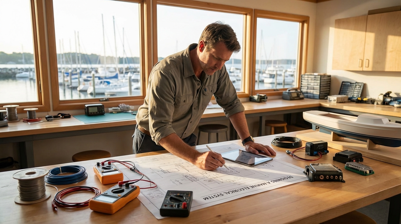
When passing cables through a bulkhead or the top of the console, use a “cable clam” or “multi-deck gland.” These fittings use a rubber bung that compresses around the cable, allowing you to pass the wire through a hole while maintaining a 100% watertight seal.
Cable Management for a Clean and Serviceable Bilge
A professional installation is defined by its cable management; “spaghetti wiring” is not just ugly, it’s a safety hazard that makes future repairs nearly impossible. Use nylon cable ties (zip ties) to bundle wires every 6 to 12 inches, ensuring they are supported and not vibrating against sharp fiberglass edges.
Follow these cable management rules:
- Label Everything: Use waterproof labels on both ends of every cable (e.g., “MFD 1 POWER”, “SONAR DUCER”).
- Service Loops: Leave a 6-inch “loop” of extra wire behind the display. This allows you to pull the unit out of the dash for service without disconnecting everything.
- Drip Loops: When a wire enters a component from above, create a U-shaped loop so that water running down the wire drips off the bottom of the loop rather than entering the device.
- Avoid High Heat: Keep wires away from engine manifolds or exhaust components.
Commissioning and Testing Your New Electronics Suite
Once the physical installation is complete, the commissioning phase involves updating firmware, calibrating sensors, and performing a “sea trial” to ensure everything functions at speed. Modern electronics manufacturers release software updates frequently to fix bugs and add features; check the manufacturer’s website and download the latest files onto a microSD card.
During your sea trial, pay attention to:
- Sonar Performance: Does the fishfinder hold the bottom at 20 knots? If not, the transducer may need a slight height or angle adjustment.
- GPS Accuracy: Verify your position against a known landmark or a secondary handheld unit.
- VHF Clarity: Perform a “Radio Check” (on a non-emergency channel like 68 or 72) to ensure you are transmitting and receiving clearly.
- Engine Data: If integrated, ensure your RPMs, temperatures, and fuel flow readings match your mechanical gauges.
Troubleshooting Common Installation Errors
Most DIY installation issues stem from poor power supply or networking configuration. If a unit fails to power on, your first step is to check the fuse at the fuse block and the inline fuse (if one was provided). Use your multimeter to check for 12.6V to 13.2V at the end of the power cable where it plugs into the unit.
Common Issues and Solutions:
- Intermittent Data: Usually caused by a loose NMEA 2000 terminator or a drop cable that is too long.
- Screen Flickering: Often a sign of undersized power wire or a loose ground connection.
- No Sonar Image: Check the transducer cable for nicks or pinches. Ensure the transducer face isn’t covered in marine growth or “antifouling” paint (unless it’s transducer-specific paint).
- Radio Static: Could be caused by LED lighting interference. Turn off all lights to see if the static disappears.
Achieving Professional Results on Your Vessel
The transition from a cluttered, unreliable helm to a modern, integrated navigation suite is one of the most rewarding DIY projects a boat owner can undertake. By prioritizing high-quality tinned wire, adhering to the NMEA 2000 backbone rules, and ensuring every connection is waterproofed with heat shrink, you build a system that can withstand the rigors of the ocean.
Remember that marine electronics are not “set and forget.” Salt, vibration, and heat are constant threats. Every six months, you should inspect your wiring for signs of chafing, tighten your bus bar connections, and check for software updates. When you take the time to install your gear correctly, you aren’t just adding gadgets to your boat; you are investing in the safety and reliability of your future voyages.
As of March 19, 2026, the technology available to recreational boaters has never been more advanced. Whether you are using side-scan sonar to find a wreck or AIS to navigate a busy shipping channel at night, your confidence in those tools starts with the quality of the installation you perform today.
📅 Last updated: